MLA-M PRO
- Home
- Magnetic loop antennas
- MLA-M PRO
MLA-M PRO
The MLA-M PRO antenna, continues the production history of the two-thread MLA-M antennas, of which almost a thousand units have been produced in nine successively upgraded versions over more than ten years.
Price
Availability:
in stock
Description
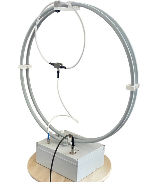
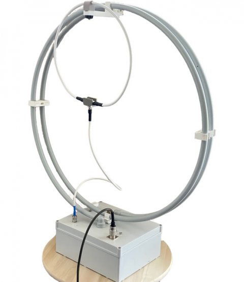
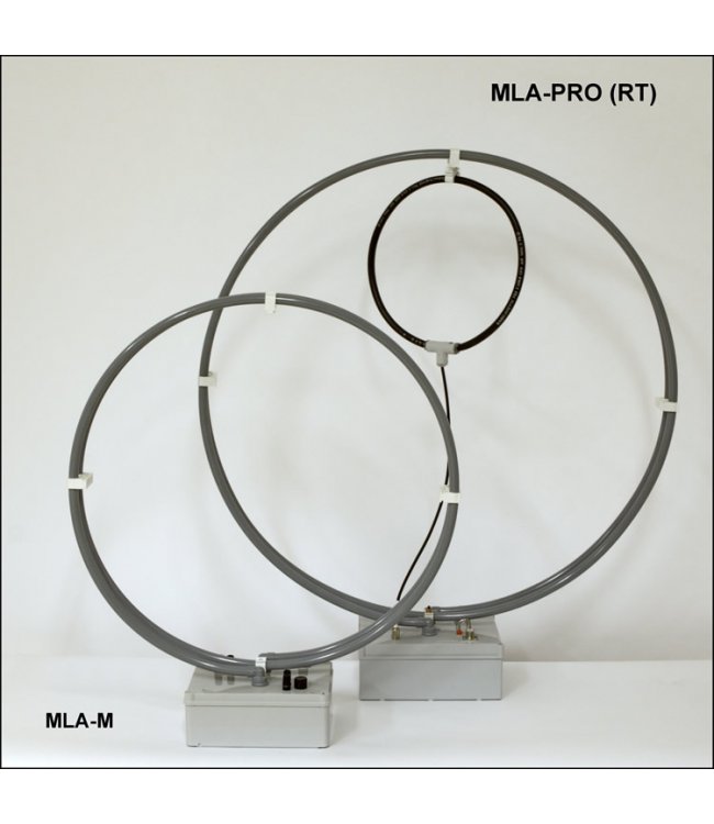 The MLA-M PRO antenna, Fig. 1, continues the production history of the two-thread MLA-M antennas, of which almost a thousand units have been produced in nine successively upgraded versions over more than ten years. All versions of the MLA-M were multiband manual tunig, and allowed amateur radio activities on shortwave from 80m to10m. A common disadvantage of all MLA-M versions is their manual tuning. While the original impedance matching by capacitive coupling simplified the MLA design, it made tuning and impedance matching by the oprator a bit more complicated, with the proximity of the body/hands changing the set frequency and impedance when tuning the MLA-M. Optimal tuning of the MLA-M without sufficient practice and routine could have been a matter of several sequential steps, hence unnecessary interference on the band.
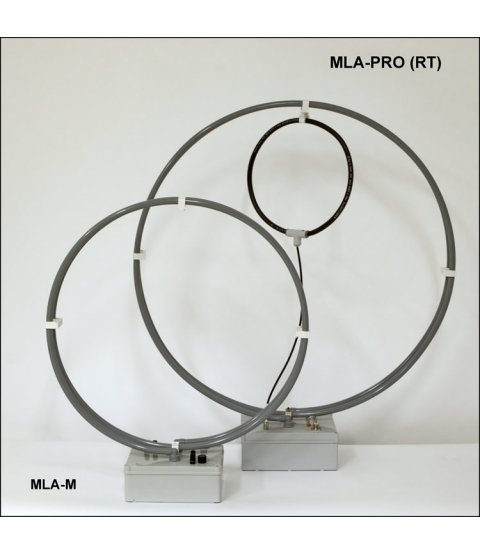
 The new type of two-thread MLA-M PRO is a remotely tuned magnetic loop antenna with FCL (Faraday Coupling Loop), which allows to move the MLA to a health-safe distance and thus to slightly increase the practical transmitter power. The impedance matching of the MLA-M PRO via the proven FCL design is easier to use (identical coupling has been used with MLA-T antennas for many years) and is less sensitive to the antenna's tuning environment (eliminating the aforementioned antenna tuning by proximity to the operator). The new version of the MLA-M PRO with remote tuning has a chance to become a worthy successor to the MLA-M antenna, which, due to its small size, good craftsmanship, and usability over the entire range of HF amateur radio bands, may have helped to bring these forgotten antenna types back into current practice not only among radio amateurs, but as can be seen for military use, Figure 2.
Principle - tuning and impedance matching of the MLA-M PRO
Magnetic loop antennas are, in basic principle, highly selective resonant antennas. They are based on a simple L/C circuit with high Q. The L coil is usually a tubular conductor. The capacitor C is usually a variable capacitance with a higher breakdown voltage. The tuning of the MLA to resonance with the received/transmitted frequency is a fundamental condition for the operation of any MLA. There are several ways to tune a magnetic loop antenna into resonance with the transmitted/received signal. As has been and will be repeatedly stated, the operation of tuning and impedance matching is a necessary condition for the operation of any magnetic loop antenna. In this respect, all MLAs are fundamentally different from other types of antennas. Tuning is most easily accomplished with a transceiver, which is logically the most readily available. Expertly and better, it can be done with an antenna analyzer or VNA, but these may not be generally available.
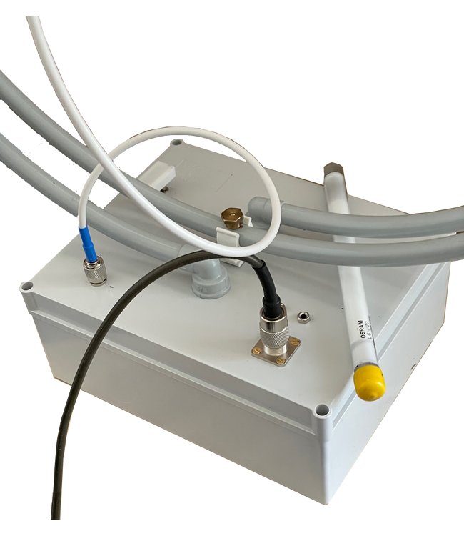
Using the TRX, we can set the MLA-M PRO both in RX mode and monitor the increase in noise/band noise in the headphones when the antenna is tuned to resonance with the tuned frequency on the TRX, or by the background on the band and the reading on the S-meter. The other option is to set the antenna in TX mode. Ideally in CW mode with the PWR reduced to a maximum of 5 W, when we can tune the antenna into resonance as a typical antenna load. We then use a sensitive SWR meter or the internal SWR meter in the TRX as a tuning indicator. We can also monitor the radiated field strength using the slide-on LED indicator that comes with the MLA. Even small 4W fluorescent tubes light up well.
With expert use of the antenna analyzer (AA), a more accurate/comprehensive picture of the physical parameters of the antenna being measured can be obtained. This is a higher league procedure and in normal practice most pure commercial MLA users will find this route unnecessarily complicated. But a few sentences on this topic as well: antenna analyzers generate a signal like a TRX, but operate at several orders of magnitude lower power. Most often we are interested in SWR, which indirectly indicates the input impedance of the antenna. For the Z-parameter, we see the antenna impedance divided into a real impedance component (Ra) and an imaginary component (jX). The advantage of tuning with AA is that we can observe the measured parameters in a wider frequency axis and see directly the spectral waveform of the MLA-M PRO parameters. In other words, we can see the impedance curve of the MLA moving along the frequency axis on the VNA. The goal is to approximate the actual 50 ohm impedance value (which is related to the characteristic impedance of the most commonly used coaxial cables and the normalized output impedance of transceivers). The attempt is to zero out as much as possible the imaginary component of the jX impedance, which de facto detunes the MLA by a complex transformation of the original MLA output impedance on the unmatched power supply. If we have an idea of what we are measuring, this will speed up the process of optimizing the impedance matching. Summarized generally in one sentence. A value of (jX) close to zero is the secret of how magnetic loop antennas work or don't work.
Remote Tuning
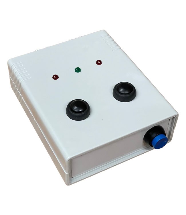
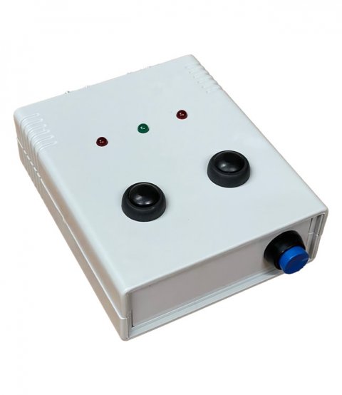
Unlike most cheaper magnetic loop antennas, the MLA-M PRO is usefully equipped with a remote tuning system. A special control box, the control box, CB4M DUO, is used for this purpose, which has an integrated turnout to separate the RF signal and control the antenna tuning. Therefore, the MLA-M PRO does not need an additional cable for remote antenna tuning. The CB4M DUO is equipped with two buttons located on the top surface of the control box. FRQ UP and FRQ DWN, a third button on the front panel switches the tuning speed - fast/slow (coarse/soft). The tuning speed of the MLA-M PRO in "slow mode" is handled by a time switched PWM. Time-dependent sequentially variable pulse width for the DC motor used to rotate the variable antenna capacitor. In coarse tuning mode, a fixed voltage is connected. The two outermost LEDs on the top panel indicate FRQ UP/DWN tuning. The middle LED indicates the switchable selectable tuning speed. The flashing green LED indicates slow tuning mode, the steady LED indicates fast tuning mode. The CB4M DUO control unit is shown in Figure 3.
How to tune the MLA-M PRO using the TRX in RX mode
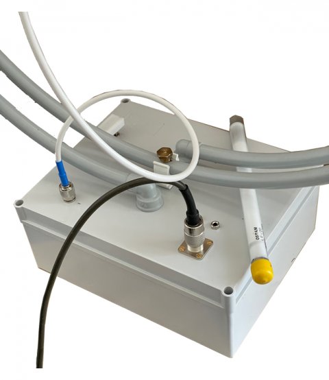
We use a 50 Ohm coaxial cable, such as an RG58 coaxial cable terminated with a PL connector, to signal the TRX and MLA as well as control the DC motor. After powering up the transceiver, we leave the TRX in RX mode tuned somewhere in the desired HAM band we are interested in working on. Switch the selected band to MLA-M PRO with two jumpers according to the table above. Depending on the current position of the tuning capacitor, we may get lucky the first time we press the FRQ UP button and within a few moments tune the antenna into resonance on the desired band and frequency. If the noise/movement on the band does not increase within a few seconds during tuning, we must hold the button for at least 20 seconds. Then the capacitor will be guaranteed to be dialed to the extreme position with minimum capacitance. The extreme positions are defined by the limit switches*. After the approximately 20 seconds required to completely retune the capacitor (from Cmin to Cmax and vice versa), stop pressing the FRQ UP button and press the FRQ DWN button. (The procedure described above rotates the capacitor from Cmin to Cmax. The MLA -M PRO antenna starts to switch from FRQ max to FRQ min. If everything is OK, we must hit a resonance point somewhere (within 20 seconds), which will register as a momentary significant increase in band noise. This is an indication that the MLA is resonating at the frequency tuned to the TRX.
*) For the planetary gear or slip gear variant, this is the time limit.
How to tune the MLA in TX mode
The method of tuning the MLA is very different from setting/ tuning other types of antennas, which are usually not tuned in any way because they are already tuned by design to the desired bands. If this is your first time holding a magnetic loop antenna, it may take some time to get used to the way the MLA works. When tuning the MLA in TX mode, an indicator LED will flash in resonance to indicate the antenna's radiated field. If we have an SWR meter connected to the coax, we will see a rapid drop and then a rapid increase in SWR again. Switching to fine tune mode on the CB4M DUO will tune the resonant frequency more accurately than we can achieve in fast tune mode. For your first experiments with the MLA-M PRO, definitely do not use the maximum power allowed! Important note: We usually cannot tell the losses not adjusted by the MLA (higher SWR value) in RX mode. Due to the RX sensitivity, the receiver amplifier can easily handle the MLA gain difference, but when transmitting, these otherwise completely identical physical MLA (RX/TX) losses are significant in that the limited power is absent in the ether. The difference in MLA losses when impedance matching an antenna at SWR of 1.0 and at 1.5 and above is usually the cause of lamentation by frustrated experimenters with these antennas, who often claim that the MLA, while good to listen to, is not suitable for transmitting. Not true. The problem lies in a misunderstanding of the physical properties of MLAs.
CB4M DUO - use with MLA-M PRO
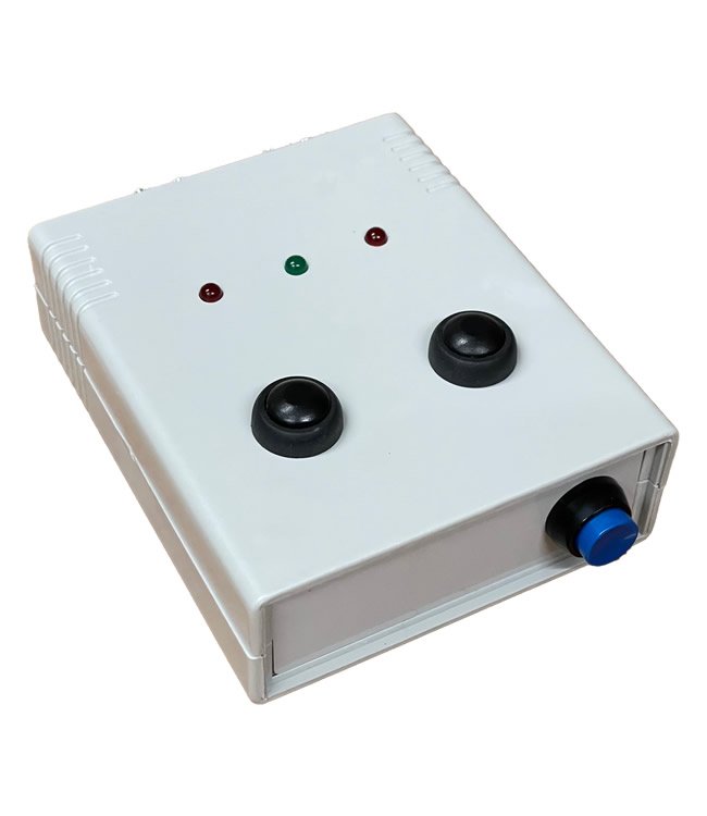
The CB4M DUO control unit was originally developed to control two MLA-S (RT/R) antenna motors. The CB4M DUO can, of course, also be used to tune the MLA-M PRO. In the function where the green indicator light is permanently lit, it is switched to the fast retune mode. Fast retune can of course also be achieved in the slow tune function, but in a more complicated way. By toggling the black button on the panel when the green light is flashing, PWM tuning is selected, where the speed of tuning is changed depending on the length of time the button is pressed. However, the CB4M DUO control unit has another advantage over the older CB4M version, automatic switching to standby mode. In this mode, the residual current of the CB4M DUO control processor drops to only hundreds of microamps, which significantly increases battery life. The standby mode switches on automatically after a few seconds of inactivity of the CB4M DUO control unit. This is indicated by the central green indicator light not illuminating. The CB4M DUO is switched back into standard operating mode by pressing one of the tuning buttons on the top of the box. The reason for the now exclusive use of battery power for the CB4M DUO is that the smaller and lighter pulse power supplies are the cause of the high pulse QRM/noise. Battery pack for CB4M DUO is included.
Important note: The CB4M DUO cannot be powered from the same power supply as the TRX. Connecting the CB4M DUO to an identical 12 V power supply for the TRX will cause damage to the CB4M DUO!
MLA-M PRO and rotators
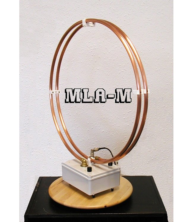
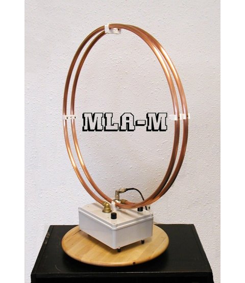
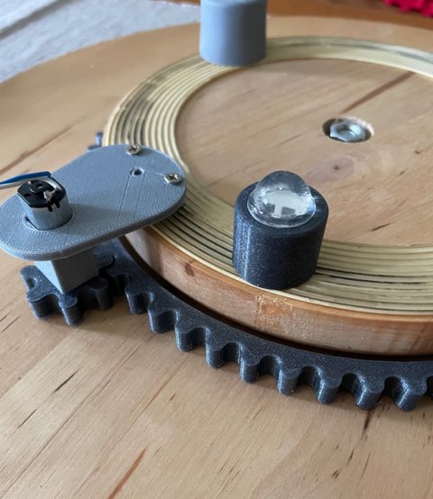
One of the earliest photographs found in the photo archive is in Figure 4, where a SNUDDA rotating serving tray was used as a base when the photograph was taken. Remarkable dajavu. Experience with MLAs has shown that when using MLAs on amateur radio bands, in addition to their remote tuning, their remote antenna rotation is advantageous. The effect can be several S. But the more significant benefit of rotating the MLA lies in the ability to suppress background interference - "digital QRM" produced by cheap mains adapters, cheap speed control motors, data transmissions over distribution systems, etc, etc. These sources of interference cause major problems in receiving weak signals especially on HF bands of higher wavelengths. Interference suppression can ideally be as low as -20 dB! Apart from the standard solution to the problem with a conventional rotator, fig.5, which is not very suitable for portable MLA, it has proven to be very useful to integrate the rotator directly into the magnetic loop antenna box, fig.6. Ideally with a smart DC switch that allows to tune, rotate, and power the MLA over a single coaxial cable. Of course, a two-way DC turnout is not entirely necessary; technically, two cables, coax and, for example, a stereo audio cable sold in various lengths (including extension spacers), which solves the problem of tuning and turning the MLA with just one auxiliary cable, is much, much easier.
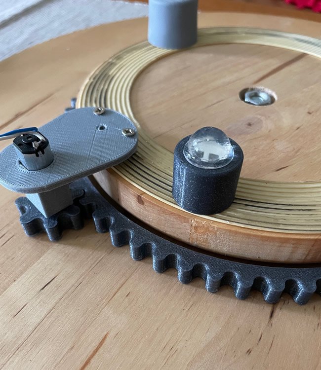
The SNUDDA rotary serving tray, lying in a warehouse of unnecessary items, has thus been reincarnated and given a new life after many years. The simplicity of 3D printing has helped. The result is an upgraded, remote-controlled rotary serving tray that appears to be an ideal rotator not only for use with the MLA-M PRO and MLA-T PRO antennas. Given the simplicity of the 3D printing solution and the possible variability of the detailed design, perhaps Fig.9 will be inspiring enough to replicate the idea. Rotator is not included with the antenna.
Technical parameters
- Frequency range/bands:3.5-5.3-7-10-14-18-21-24-28 MHz
- Impedance:50 Ohm
- Maximum PWR:25 W
- SWR max::1.2
- Input connector:PL
- Dimensions:63x75x18 cm
- Weight:2,8 kg
- Loop diameter:60 cm
- Accessories: CB4M DUO, Battery pack for CB4M DUO, Rotator NOT included
Band switching jumpers
- Central rotary jumper OFF and BLUE jumper ON: 3.5 MHz
- Central rotary jumper OFF without BLUE jumper: 5.3-7-10-14 MHz
- Central rotary jumper ON without BLUE jumper: 18-21-24-28 MHz
