MLA-ER 2026 (20 m)
- Home
- Magnetic loop antennas
- MLA-ER 2026 (20 m)

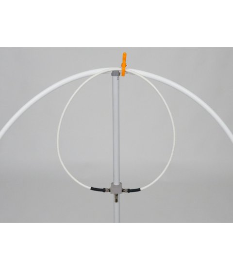
MLA-ER 2026 (20 m)
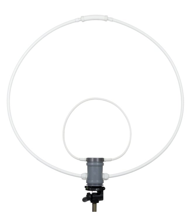
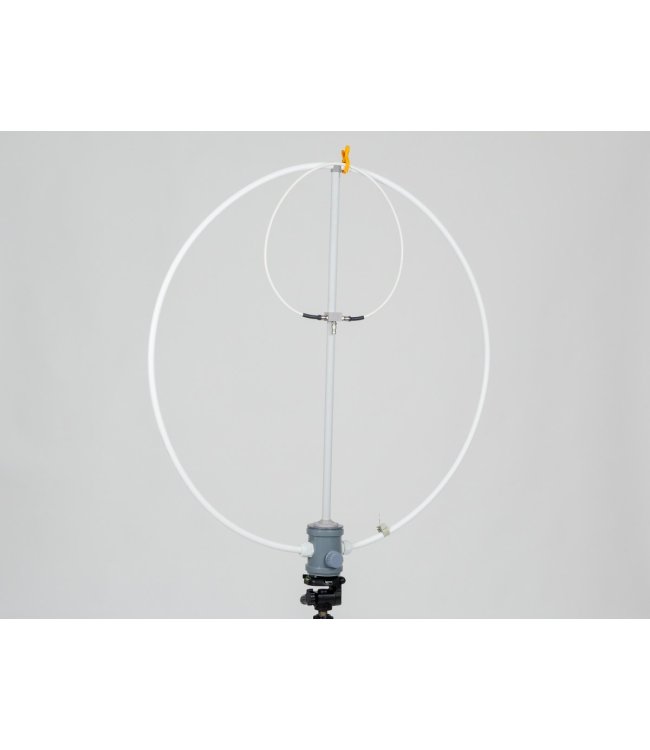
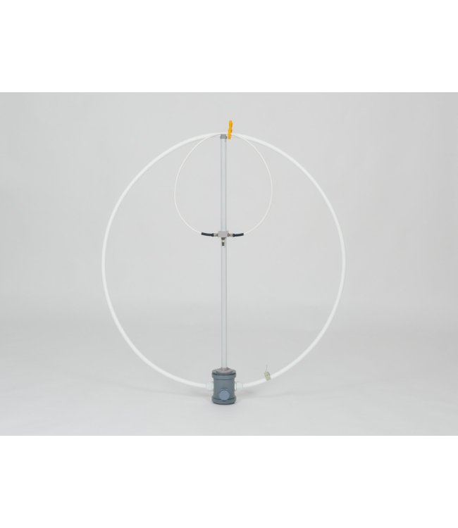
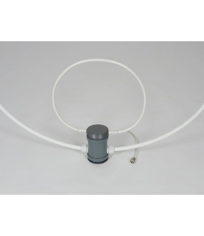
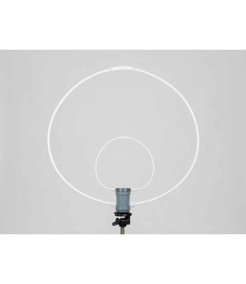
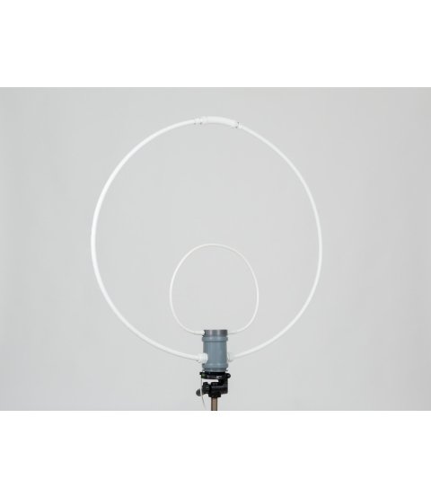
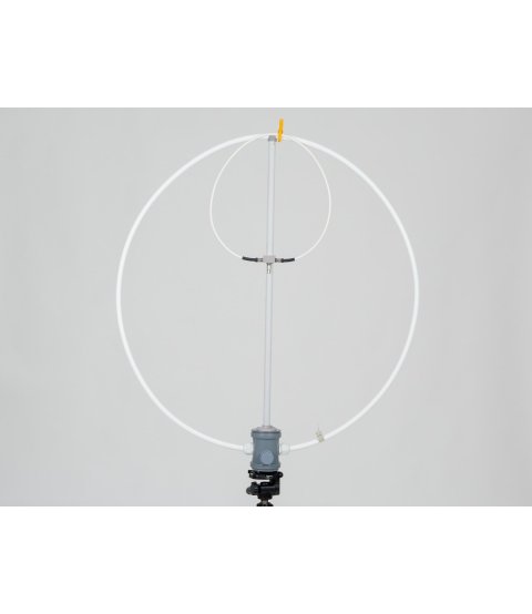
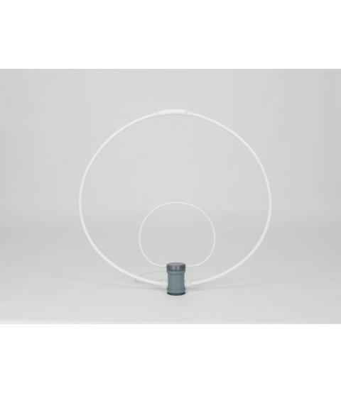
The MLA-ER 2026 (20) is the simplest magnetic loop antenna by OK2ER: single-band (20 m), 100 W, without a tuning capacitor – the resonant circuit is formed by the loop itself, made from PEX-AL-PEX tube with a capacitive stub inside. This MLA is designed as an educational model, yet it is a fully fledged antenna: with 100 W, it can be used to make contacts over thousands of kilometres from a flat, balcony or a temporary QTH.
Price
Availability:
in stock
Versions
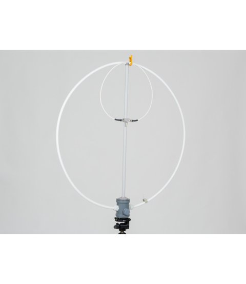
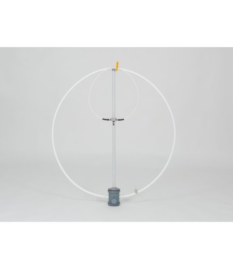
Two versions: top tuning / bottom tuning. The specifications are identical for both.
Please state your preferred version in the order note. If you have no preference, leave the order note empty and we will send one of the versions.
Key features
- Maximum usable power 100 W, even continuously (FT8).
- Loop diameter approx. 0.9 m, weight approx. 1 kg.
- No tuning capacitor – the capacitance is provided by the stub inside the tube.
- Matching is done by rotating and shaping the FCL: SWR typically 1.0–1.1.
- 1/4" tripod thread; stands on its own without a tripod.
Versions – comparison
Two versions of the MLA-ER 2026 (20) are available with identical specifications; they differ in the tuning element and the connector type:
| Top tuning | Bottom tuning | |
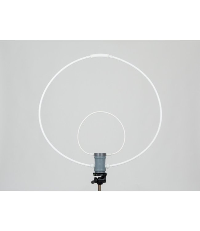
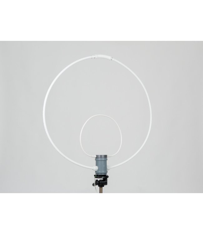
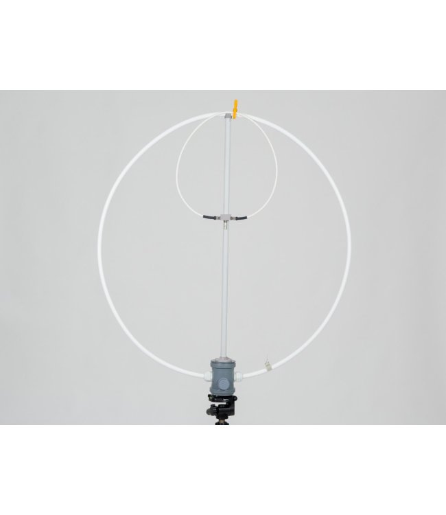
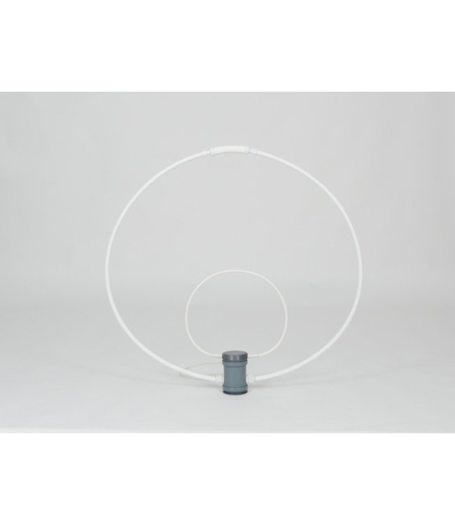
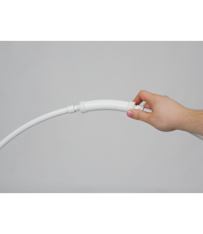
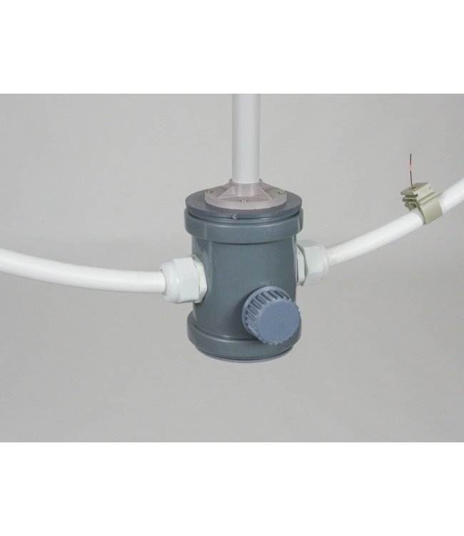
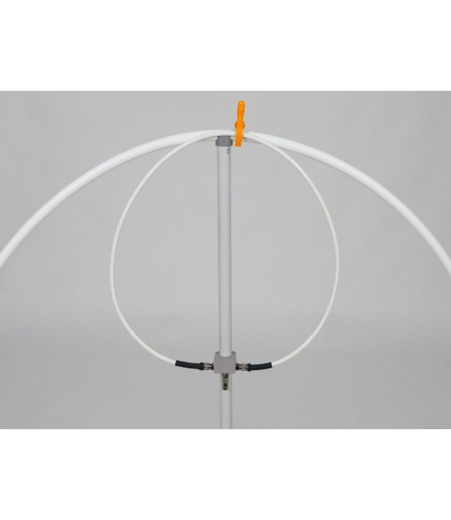
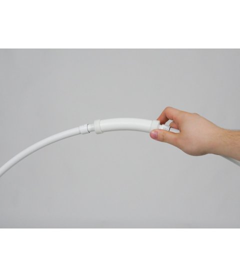
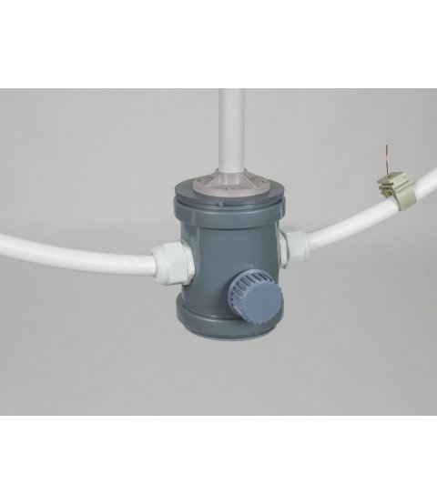
| Tuning element | tuning sleeve fitted on the upper part of the loop, sliding between two stops; a shift of 1 cm ≈ 100 kHz | tuning knob on the front of the base – turning it moves the tuning segment inside the base |
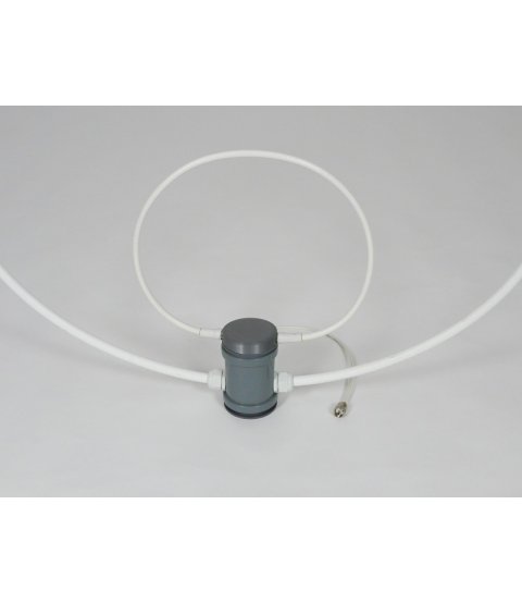
| FCL | extends from the top of the base; adjusted by rotating it, shaping it and bending it out of the plane of the loop | secured in the FCL holder on the support rod; adjusted by rotating it, shaping it, sliding it along the rod and bending it out of the plane of the loop |
| Connection | permanently attached short coaxial lead terminated with a PL plug (PL-259) | BNC connector on the underside of the FCL holder; coaxial cable not included |
Who it is and isn't suitable for
Suitable for
- flats, balconies, holiday cottages and temporary locations where a wire antenna is not an option;
- CW, FT8 or other modes operated around a fixed frequency;
- anyone interested in the MLA principle (educational model).
Not suitable for
- operation with frequent retuning (e.g. SSB) – a frequency change of more than approx. 15 kHz requires retuning;
- permanent outdoor installation – it is not weatherproof;
- operation without an SWR meter or analyser, operation without manual tuning or at power levels above 100 W.
Description
An antenna without a traditional tuning capacitor
Every magnetic loop antenna is an L/C resonant circuit with a very high Q factor. In conventional MLAs, the capacitance is provided by an air or vacuum capacitor – the expensive and sensitive part of the antenna. The MLA-ER takes a different approach: the capacitance is provided by the loop itself. A length of coaxial cable, the capacitive stub, is inserted into both ends of the PEX-AL-PEX tube; the cable's shield and the aluminium layer of the tube act as the capacitor plates, while the cable sheath and the tube wall act as the dielectric. The result is an antenna in which the MLA principle is immediately apparent.
Two versions, one principle
Fine tuning is provided by a small variable capacitance. With top tuning, this is a tuning sleeve fitted at the top of the loop: a shift of 1 cm corresponds to a frequency change of approximately 100 kHz, and the range between the stops covers the entire 20 m band. With bottom tuning, the tuning knob on the base moves the tuning segment inside the base; the range between the stops again covers the entire 20 m band. Each antenna is tested from one end of the band to the other before dispatch.
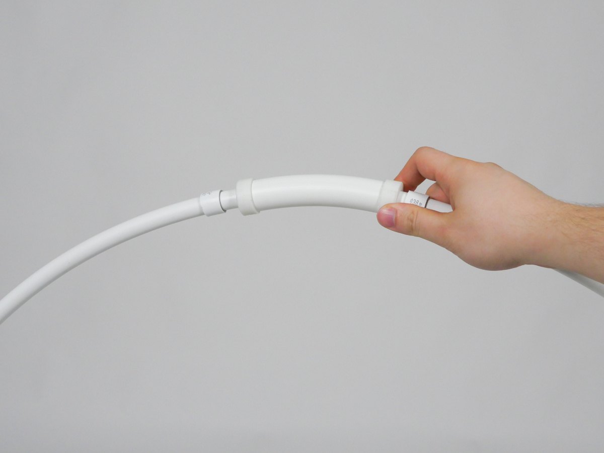
Top tuning
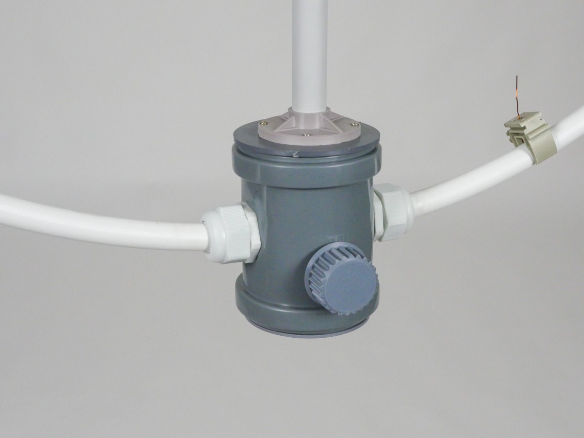
Bottom tuning
The matching on which the MLA depends
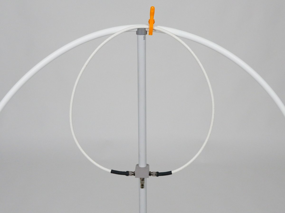
Energy from the transceiver is transferred to the main loop by the FCL (Faraday Coupling Loop). Its orientation and shape determine the matching to 50 Ω – and this is precisely what matters with an MLA: if the SWR is poor, part of the power is converted into heat and the antenna 'does not work', even if it is tuned precisely. The FCL of the MLA-ER 2026 can be adjusted by rotating it, shaping it, bending it out of the plane of the loop and, with bottom tuning, by sliding it along the support rod; a correctly matched MLA has an SWR of 1.0–1.1.
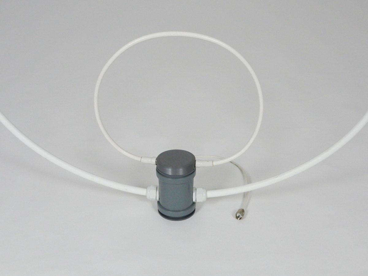
Top tuning
Bottom tuning
What to expect from MLA-ER 2026 on the band
With a diameter of approximately 0.9 m, the MLA-ER 2026 is efficient enough on the 20 m band to make contacts over thousands of kilometres – even with less than the full 100 W, from a flat or a balcony. Unlike a dipole, MLAs also work low above the ground. The high Q (approx. 200) means a bandwidth of approximately ±15 kHz for an SWR < 1.5: this is no limitation for FT8 and other fixed-frequency modes; with CW, retuning is needed occasionally, with SSB frequently. In RX mode, the selectivity is an advantage – the antenna suppresses strong signals and some of the interference outside the tuned segment, and a source of interference can be suppressed further by rotating the antenna. Metal objects nearby, such as window frames, railings, radiators or other antennas, detune the MLA. The MLA-ER 2026 is not weatherproof: rain, damp and dew change the tuning.
Where it came from
The MLA-ER design was first described by OK2ER in 2018 in the book Magnetic Loop Antennas Slightly Different Each Time. The MLA-ER 2026 is an improved version of this original design.
For those who want to experiment and build
The antenna is single-band only because of the length of the capacitive stub. Anyone with an antenna analyser can, following Chapter 10 of the manual, make their own stub and operate the same MLA on 17, 15, 12, 11 (CB) and 10 m. On these higher bands, the efficiency of a loop of the same diameter increases significantly. The original stub is kept for returning to the 20 m band; the manufacturer accepts no liability for modifications carried out by the user.
Package contents
| Both versions | |
| Included | antenna; user manual |
| Not included | tripod; antenna analyser; coaxial cable to connect the MLA to the transceiver |
| Equipment required | HF transceiver, ideally with an SWR meter; 50 Ω coaxial cable with the connector matching the chosen version (top tuning – PL, bottom tuning – BNC) |
| Optional | tripod with a 1/4" camera tripod thread; antenna analyser (strongly recommended – tuning is possible without one, but it is time-consuming) |
Safety
- Do not touch the antenna while transmitting, especially at full power, when the RF voltage at the ends of the loop is in the order of kV. There is a risk of RF burns.
- When transmitting, keep a safe distance from the antenna – the higher the power, the greater the distance required. The minimum distance during transmission is 1 m.
- Do not transmit if there are people or animals near the loop. No one must have their head or any part of their body inside the loop.
- People with a pacemaker or other implanted medical device must not operate the antenna or remain in its vicinity during transmission without first consulting a doctor.
- Strong RF magnetic fields pass through walls and may interfere with, reset or even damage nearby electronic equipment (computers, chargers, network devices).
- Always tune the MLA at low power (max. 5 W). Only increase the power to full after tuning and checking the SWR.
Frequently asked questions (FAQ)
Can I use an antenna tuner instead of adjusting the FCL?
No. The matching is done by the FCL; after tuning, the SWR is typically 1.0–1.1. A tuner cannot correct poor matching – part of the power is converted into heat.
How wide is the bandwidth?
SWR below 1.5 within approx. ±15 kHz. Beyond that, just retune; the FCL usually does not need adjusting after a small retune.
Which version should I choose?
The specifications are identical; the versions differ only in the tuning method and the connection (see the comparison table). Bottom tuning is tuned with the knob on the base and has a BNC connector; top tuning is tuned by sliding the sleeve on the loop and has a fixed lead with a PL plug. We would like to know which version suits you better – your feedback will help us decide which version to continue with.
Does it work on other bands?
Not as supplied. By replacing the capacitive stub with a shorter one, the antenna can be operated on 17–10 m, including CB (see Chapter 10 of the manual; an antenna analyser is required; the manufacturer accepts no liability for modifications).
The SWR changed after I moved the antenna.
That is normal – the antenna is tuned in place. After moving it, rotating it or changing its surroundings (even a person standing near the antenna), retune and readjust the FCL.
Do I need an antenna analyser?
It is not essential, but it is recommended. Without one, tuning is done by listening for maximum noise and using the transceiver's SWR meter – possible, but complicated and time-consuming.
Does it work indoors?
Yes, even low above the ground. In reinforced concrete buildings the efficiency of an MLA is lower; metal objects nearby detune the antenna.
What kind of tripod can I use?
Any camera tripod with a 1/4" thread; tripod not included. The base also stands on its own on a table or on the ground.
Download
User manual – top tuning (PDF)
User manual – bottom tuning (PDF)
Technical parameters
- Bands:20 m (14 MHz)
- Tuning range:the entire 20 m amateur band
- Max. usable power:100 W, continuous (including FT8)
- Tuning:
manual on both versions; top tuning – sliding tuning sleeve on the loop (a shift of 1 cm ≈ 100 kHz); bottom tuning – tuning knob on the base, which moves the tuning segment inside - Matching:
FCL (Faraday Coupling Loop); matching by rotating and shaping - Achievable SWR:typically 1.0–1.1
- Bandwidth:SWR < 1.5: approx. ±15 kHz
- Loop diameter:approx. 0.9 m
- Dimensions (overall):
approx. 0.9 × 0.9 × 0.15 m (width × height × depth) - Weight:approx. 1 kg
- Input connector:
top tuning – PL plug (PL-259) on a permanently attached short coaxial lead; bottom tuning – BNC connector on the FCL holder - Input impedance:50 Ω
- Mounting:
1/4" camera tripod thread in the bottom of the base; the base also stands on its own on a flat surface - Materials:
main loop PEX-AL-PEX Ø 16 mm (the aluminium layer is the conductor); plastic base - Use:
indoor, balcony, temporary location; not weatherproof – not for use in the rain, not as a permanent outdoor antenna