MLA-C v.5 KIT
- Home
- Magnetic loop antennas
- MLA-C v.5 KIT
MLA-C v.5 KIT
MLA-C v.4 KIT is replaced by MLA-C v.5 KIT for the same price. The frequency range is extended by two additional bands, 10 MHz and 14 MHz, similar to the newer, smaller size MLA-V KIT.
Description
This magnetic loop antenna was originally designed by OK2BUH, widely improved by OK2ER.
It is destined for 3.5 to 7 MHz operation, with up to 100W input. It is also usable at 5.3 MHz. The frequency range is extended by two additional bands, 10 MHz and 14 MHz.
The antenna is remotely tuned by a DC motor with a flexible coupling to the high-voltage variable capacitor. Tuning is done by an inteligent PWM by CB4M driver. On 3.5 MHz, its function is lightly compromised, at 7 MHz it is suitable also for DX communication.
MLA-C is very huge among other commercial MLAs, so the shipping is quite complicated.
The advantage is an easy and fast assebly, from unpacking to operation a dozen minutes, best in two persons
As it can be completely disassembled, it can be assembled anywhere the MLA-C could not be delivered. It is ideal for the use in lofts with narrow passages.
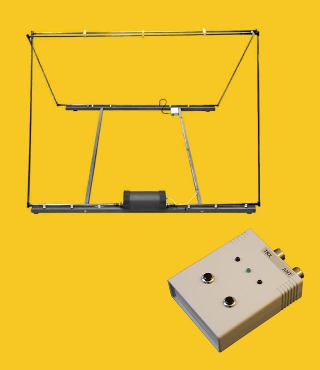
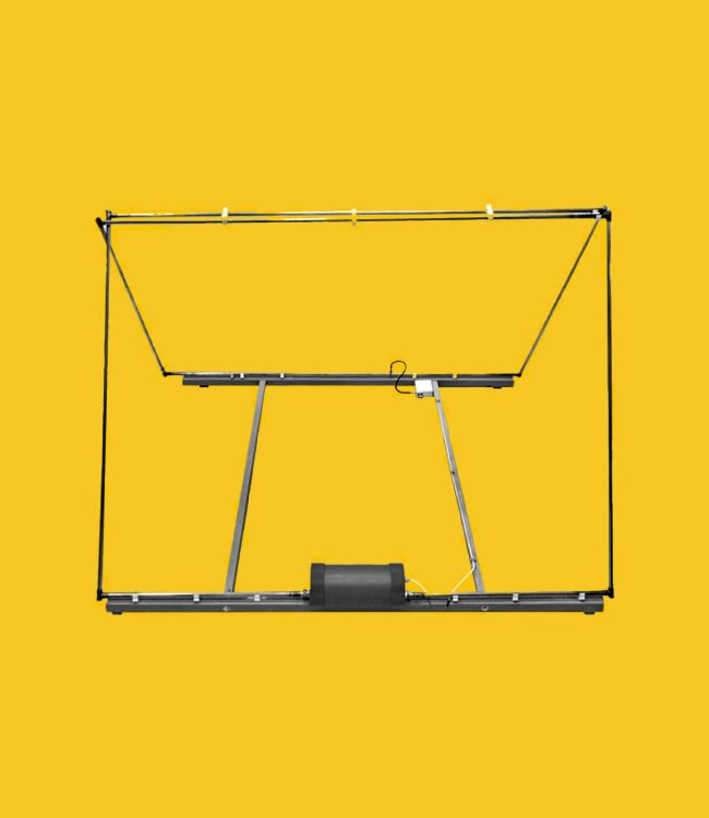
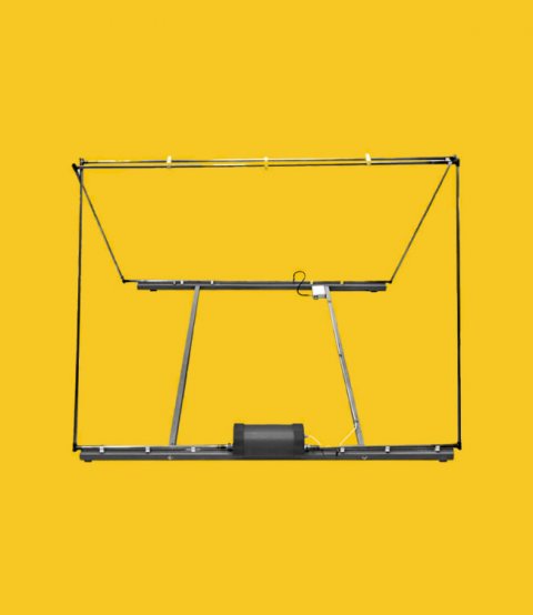
MLA-C (as Car) is a magnetic loop antenna designed for two-band operation, mostly for a portable use in 40m and 80 m band, with a RF power input up to 100 W. This makes it different from most of similar antennas. The MLA-C antenna is designed for mobile operation in /p, /m and /mm modes. The MLA-C KIT is ideal for small expeditions to exotic destinations. It can also be used as a stationary base antenna I urban locations where installing long-wire antennas is not possible. It can be unfolded from 2D to 3D shape in 3 minutes, so it can be also used on larger balconies or porches of rental houses.
The MLA-C antenna is transportable on a car or boat, and offers a high radiation efficiency for space- wave propagation by ionosphere reflection, over short ad medium distances (NVIS). Compared to other mobile shorted verticals, MLA-C is typically 10-15 dB better. As a stationary base antenna, the MLA-C is comfortable on 80 m band while on 40m it is just the best!
MLA-C was improved from the earlier version to achieve a smooth tuning over 40 through 80-meter bands, now without manual switching. Remote tuning works over one single frequency range.
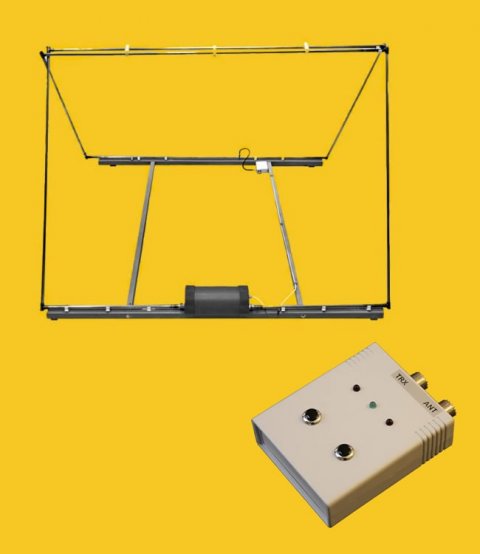
The remote tuning in MLA-C is made with a 12VDC motor with 1:600 gear, fed through the coaxial feeder cable and a DC bias tee. Due to the high antenna selectivity (several kHz typically), the high gear ratio is not enough, so a PWM pulse motor feed is used. Details can be found in CB4M driving-unit and MLA-C description. Only the single RF cable is used to feed the MLA-C as well as to tune it. At the TRX side, the DC bias tee is located in CB4M control box, outdoors the other DC bias tee is located in the weatherproof box attached to antenna frame. A common AC/DC 12V, 1A adapter is included. For the mobile use, there is an optional K1 feeder cable.
Feeding the MLA-C. The RF cable connecting a TRX with the K2 control box is included, its length is 2 m and PL connectors are used. To connect the K2 control box to the antenna, any good coaxial cable can be used, 50 Ohms, with PL connectors, e.g. RG 213. For short connections, also RG58 can be used. This “longer” feeder cable is not included in the delivery.
IMPORTANT CAUTION
The MLA-T can be used indoors with a maximum RF power input of 10W. In no way it might be used indoors with more than 10W! Make sure you are not exposed to the RF magnetic field for a longer time. Although there has been no scientific proof of side effects of the RF magnetic field, it is clear that a long-time exposure to the radiating antenna would not be healthy. If 100W input is considered, the operator should stay away at least 5 m from a MLA-T. The RF magnetic field does pass through walls!
When the MLA is fed with a RF input power, do not touch it! It would not kill you but may cause local RF burns . High RF magnetic fields can complicate EMC as common electrical shielding (without a magnetic material) is not effective enough for the magnetic component. This holds for all magnetic loop antennas.
Operators with implanted heart pacemakers should avoid using or approaching MLA-2B.
Technical parameters
- Control box connectors:2x PL
- Frequency range:3.3 to 7.4 MHz
- Frequency range:10 MHz
- Frequency range:14 MHz
- Input impedance:50 Ohm
- Maximum power:100 W
- MLA input connector:PL female
- SWR when tuned:max. 1:1,1
- Weight:8 kg